800 bpi NRZI and 1600 bpi PE, 45 ips, 9 track, equipped with (optional) formatter F1000
Bought in the 80's for and used with an MC68030(?) based Unix system (yes, really SCO “Unix”) for data transfer to/from “mainframe computers”
In the early 1990's it came into my possession (together with that Unix system) but was never really used and hence was put in the barn to collect dust...
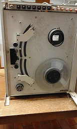
In January 2017 I went into the barn, dug it out from the dust, used a lot of compressed air and here is how it looked (mounted in the original shipping frame it came in from Ampex):
The operator panel's push-buttons were mostly fused to the black plastic frame around them. First I thought of some funny heat event (but that would have logically taken down the barn with it), but then I noticed that the plastic part was very sticky and I now conclude that the plasticizer has migrated out and worked somewhat like solvent or glue. Hence above picture is without the buttons and the frame around the operator panel. The switches themselves are OK.
Several indicator light bulbs need replacement, they are either totally corroded, fell apart when I removed them or are just broken. I ordered replacements that cme close to the original ones: 14V/80mA, BS9 socket.
The rubber ring that is part of the file reel holding mechanism is a bit expanded and crackled but still works.After checking and adjusting the transformer tap connections to be 230 Volts, applying power went without any “boom”. Loading a tape worked. Loading at this drive means you manually thread the tape from the file reel through between the 4 rollers at top, around the top leftmost roller, then vertical down through the head assembly, around the capstan and through another 4 rollers to the fixed reel and wind it around there for like 3 revolutions.
Then press the “LOAD” button. The two arms will then move and tension the tape. The drive will search for the BOT reflective marker and stop and become READY and ONLINE. This worked fine.
In OFFLINE mode one can manually FORWARD or REVERSE the tape at 45 ips, that also worked well. The capstan starts and stops extremely fast and the arms together with the reels try to cope with that.
What did not work well at all was REWIND, which occurs at a much higher speed than 45 ips. At any case the reels did not cope with the associated acceleration properly and the drive (fortunately) went into ERROR and did not tear the tape. Since all this happens extremely fast, it was not possible to exactly see what was wrong.
After a long search it turned out that the integrator that should limit the capstan's acceleration/deceleration did not do its job because a 2µF electrolytic capacitor was not a capacitor any more. After replacing all capacitors of that same type (all proved to be dead) in the drive electronics REWIND works now. Also noticeable, the movement of the reels was more smooth than before (same capacitor also is in the PID controller of each reel).
Its a well known issue with old electrolytic capacitors that they can dry out and loose all their capacity. Here it seems to have affected only that particular type of capacitor. All other types are still within their values. But the others are hermetically sealed electrolytics.
At that time I also noticed that the instruction manual and schematics I had are not exactly for this model of drive. Also I had no manual at all for the formatter. And nothing to be found in the internet!
Connecting an oscilloscope to the raw read data showed pulses when the tape was moving.
Well, I then thought I would have to use the raw data and deal with it myself either with an FPGA of by CPU power.
Other work (fortunately, in after sight) kept me from doing it.
Having some spare time in Juny 2017 and remembering I would have a nice 85cm high 19" rack with rollers in the barn, I decided to mount the drive in that rack so I could roll it around in the lab for easier work on it.
To my surprise the exact manual for that drive and for the formatter were sitting right on top of that rack! Great!
Using the formatter will really make it very simple to read and write blocks on the tape in 800 bpi NRZ or 1600 bpi PE. Basically you just give a READ&GO signal and then all drive control, timing, parity and CRC checking, read de-skew of PE data is handled by the formatter. You only need to cope with roughly 70 Kilobytes/second of data rate at 1600 bpi.
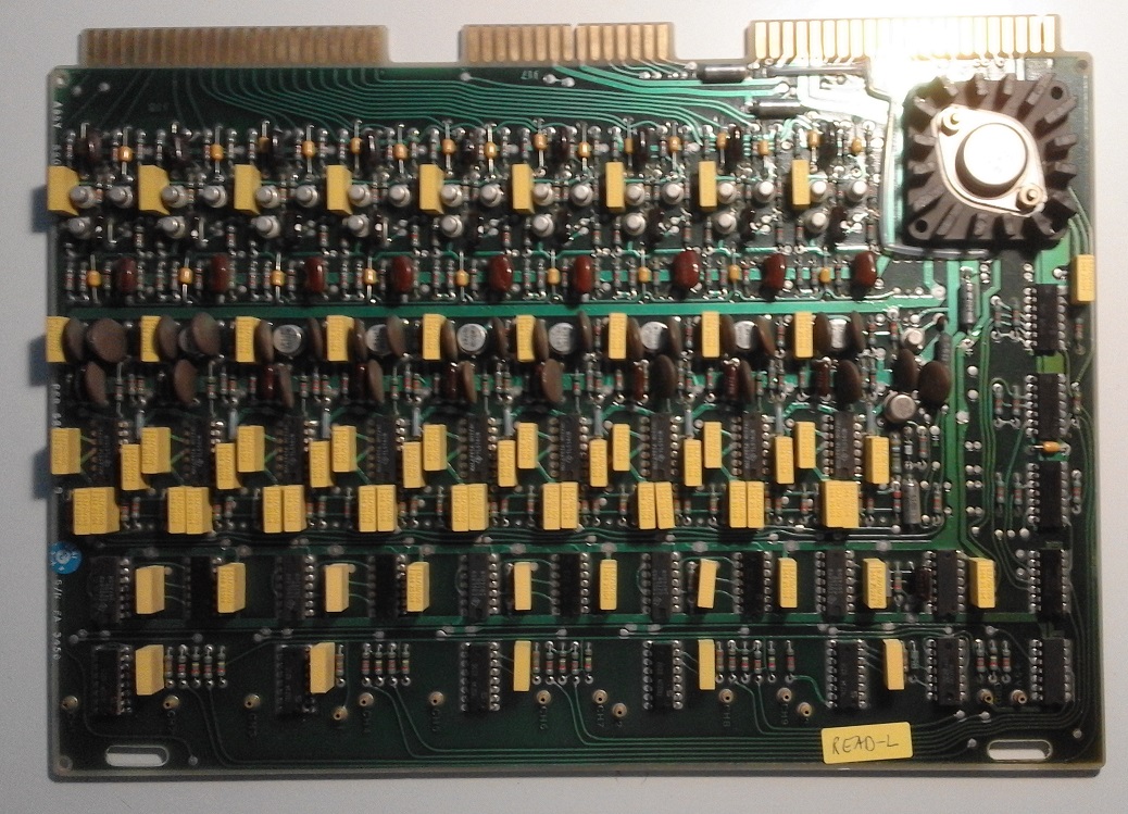
As it turns out, the same type 2µF capacitor type is used extensively in all analogue circuitry of the read amplifiers. 7 capacitors per track are used, so I need to replace a total of 63 of them plus a few here and there. (All samples I de-soldered and tested proved to be dead).
Looking closer at the circuit diagrams and the capacitors I noticed that they all must be and are indeed are bipolar capacitors.
Bipolar electrolytic capacitors are hard to find. But nowadays ceramic capacitors with 2.2µF are even smaller than those electrolytic ones, I ordered 100 pieces of them and the necessary 2x36 card edge connector to the formatter (still a standard product):
Arrival of the parts:
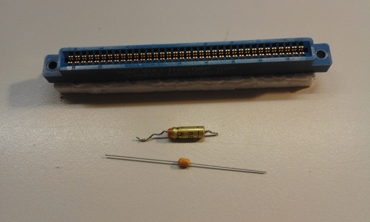
See the size difference! Old electrolytic capacitor 2µF/50V and
new ceramic capacitor 2.2µF/50V.
PE Read Amplifier before:
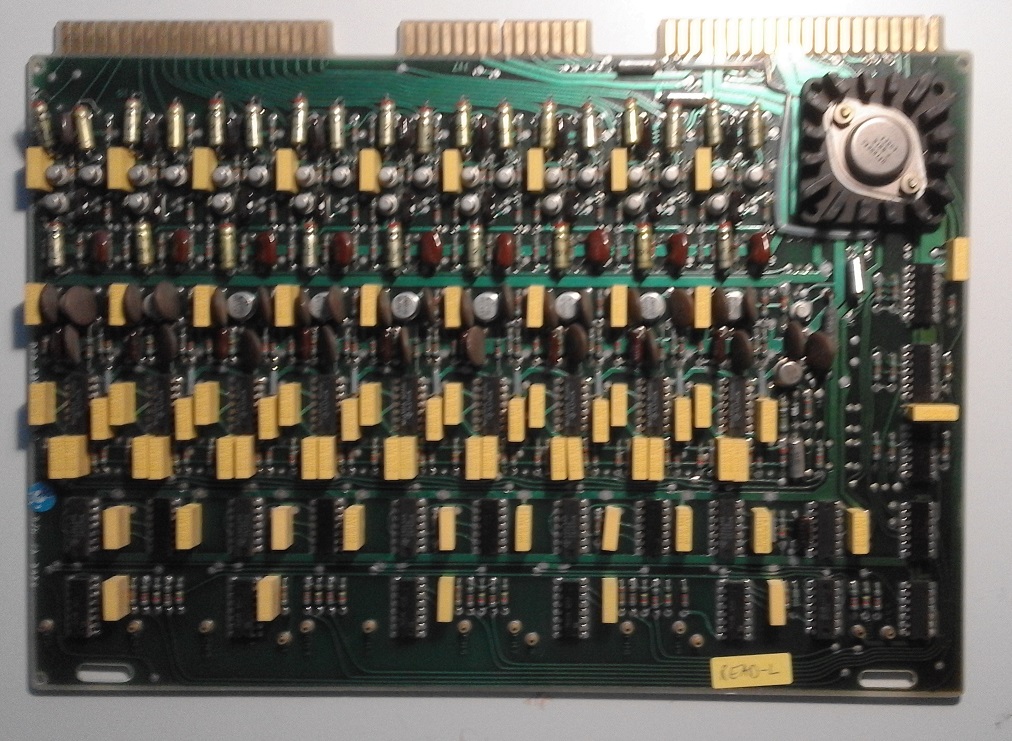
Those (originally fitted) 2µF are much too long for the through-hole distance, so I
assume that other capacitor types were planned and
Ampex used those rubber sealed electrolytic capacitors for cost or
availability reasons. All other electrolytic capacitors on those
boards are of a much better glass sealed type and have not lost
any capacity.
PE Read Amplifier after:
Notice how nicely the new capacitors fit!
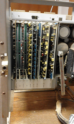
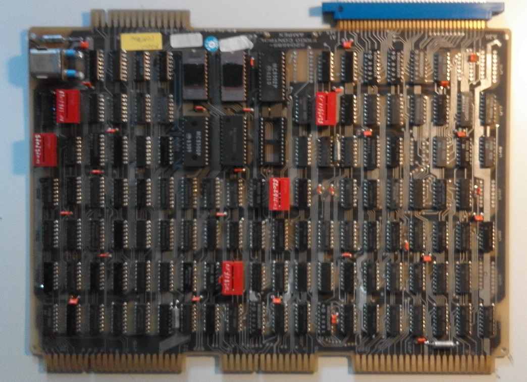
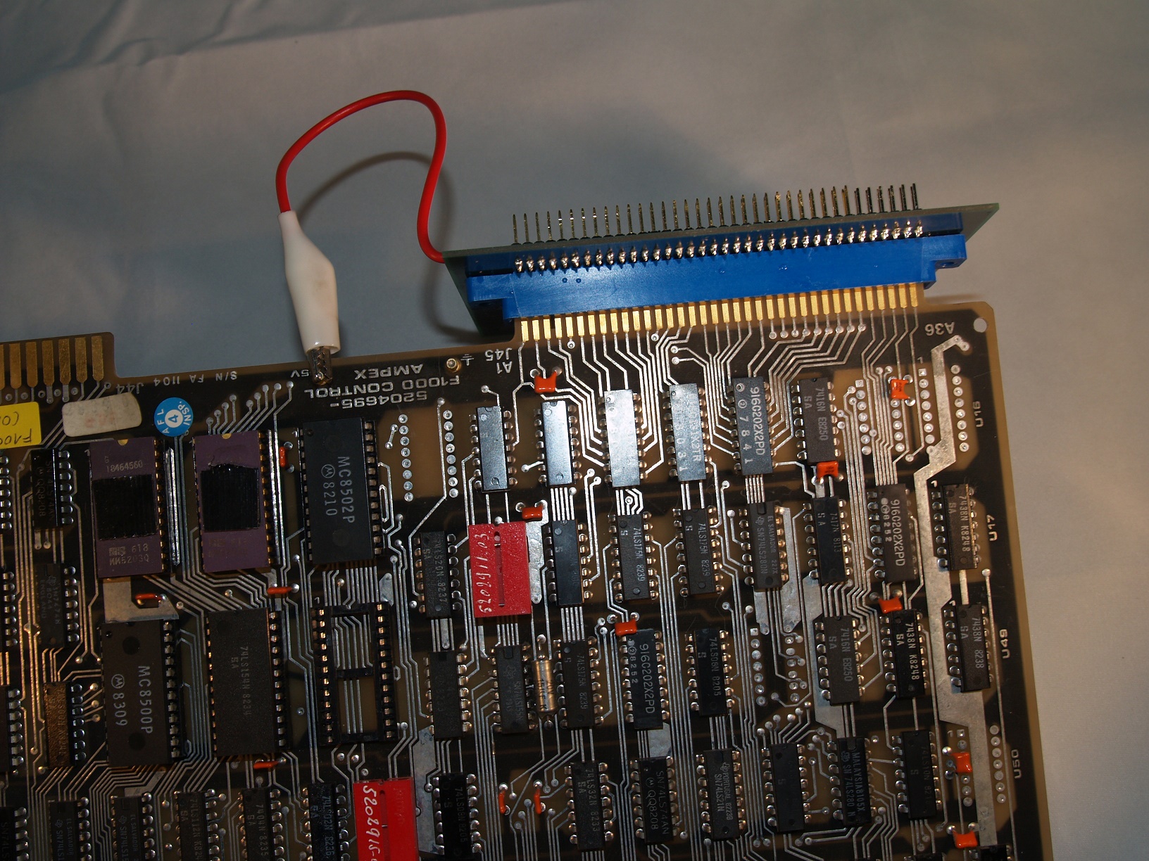
The formatter/controller consists of two boards:
One is for control and timing, the other is for encoding/decoding and contains hardware FIFO circuits and 1 bit error correction at PE. It has a discrete built state machine around a pre-settable counter and EPROMs.
The control board is complete, despite my initial fear that the empty socket indicated a missing part. But it is an optional item not required.
It turns out, of the two UV-eraseable EPROMs, one is for NRZ and one is for PE operation.
There is no microprocessor on the board, all processing is done by a state machine in discrete logic! This board is a specialized computer on its own!
The red boxes contain “options”. Usually just wires or resistors that are dependant on the drive's tape speed (timing for gaps, file marks, id burst and such).
The MC8500 and MC8502 are interesting chips: Parity and CRC generators/checkers.
The crystal is 5.786 Mhz, it is an integer multiple of the data rate and timing.
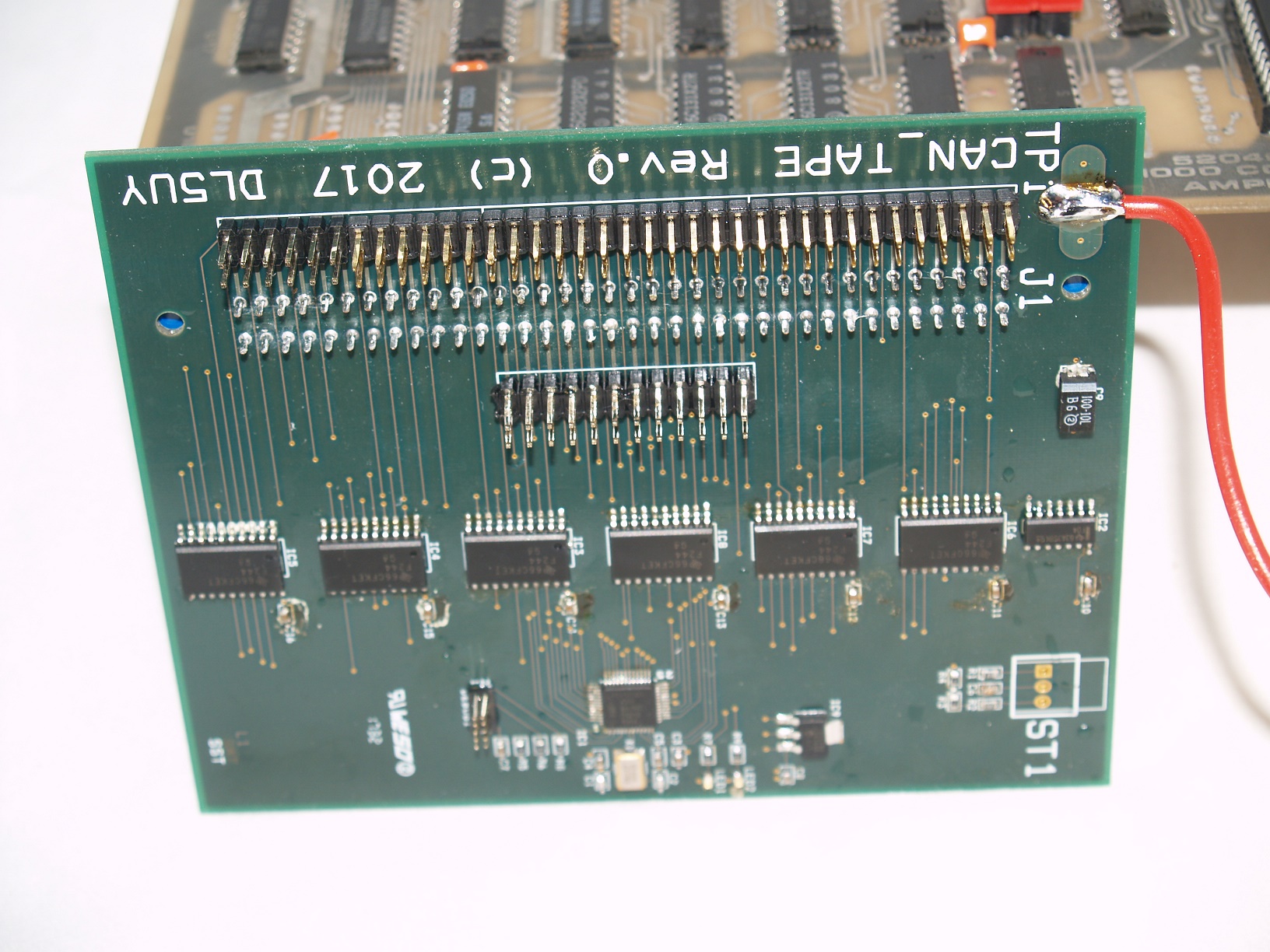
The formatter has a total of 48 signal lines brought out on this 2x36 card edge connector. They can be grouped like this:
Addressing and enable
Commands
Status
Read data
Write Data
All Signals to or from the formatter are low active.
Signals from the formatter are TTL open-collector outputs with 2k pull-ups to +5V. They should be terminated at the CPU end with a 220/330 Ohms resistor combination. For very short distances, no extra resistor should be required.
Signals to the formatter are terminated in the formatter with a 220/330 Ohms resistor combination and as such must be driven by outputs that can sink at least 22 mA. Since a 3.3V CPU cannot drive those signals directly, SN74F244 drivers will do that part.
I have put some constraints on the design:
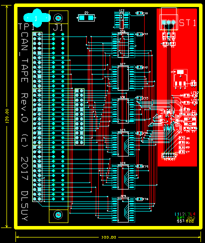
It plugs directly onto the formatter by J1. To accommodate possible
required patching, each signal from or to the formatter goes
through a jumper.
The CANbus connects to ST1, and 5 V power is “stolen” from the formatter itself.
Notice the rather large SMD 74F244 chips in contrast to the really small LPC11C24 CPU!
Programmed in “C”.
Naturally based on the existing framework I use for projects with that CPU, consisting of NO operating system, just good IRQ handling and a CANopen stack. The “main()”, after initialisation stays in a “while(true)” loop doing only the non time critical housekeeping.
Everything else is done in IRQ functions.
So the only really new parts are the IRQ driven data transfer (70k IRQ/s is no problem with that CPU) and packing the data into CAN frames.
For the write direction a whole record would have to be buffered before actual writing to the drive starts. Write is of no concern right now.
Minor housekeeping to receive commands and send status via CAN is also required.
Note that my current plan is NOT to do any data translation at this level. Only parity, LRC and CRC will be checked or generated by this CPU or the formatter. So there will be 8 bits of data on the CANbus, not 9 bits which would be inconvenient.
The software framework was written while waiting for the board...
Needs to be stuffed with parts:
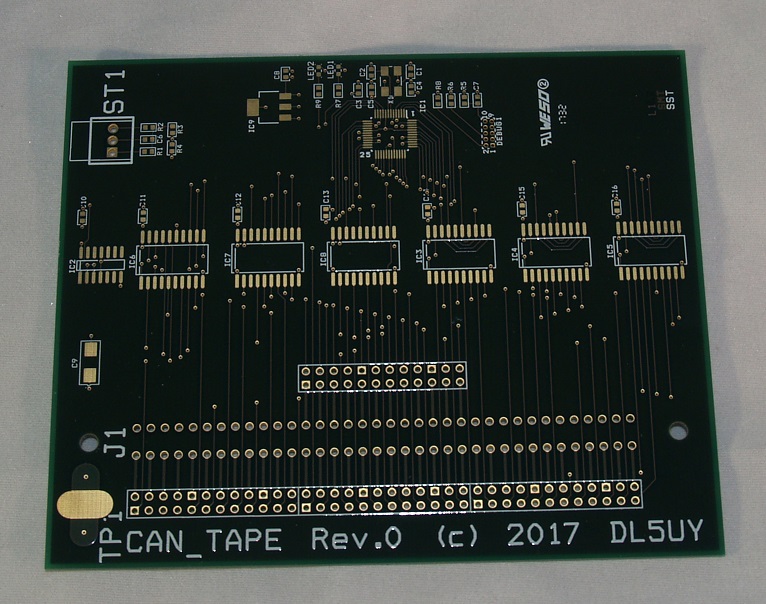
Now with parts:
and attached to the formatter:
First Light is a term from astronomy.
After writing the basic software to interact with the formatter, a small command interpreter was used on the LPC11C24 to exercise the formatter. After some debugging, the drive could be controlled and records could be read.
Initially the records seemed to hold garbage until I realized, that R0 is the most significant bit. Reversing the bit order showed ASCII, EBCDIC or just binary encoded records (depending on the tape that was read)
Within hours, the “small test software” on the LPC11C24 grew into a full B7700 library tape decoder. That still did not put the small LPC11C24 to its limit, 10k code and 9k data (including record buffer and translate-tables.)