based on work by Grant Searle:
http://searle.hostei.com/grant/Multicomp/index.html
which is hereby acknowledged and greatly appreciated.
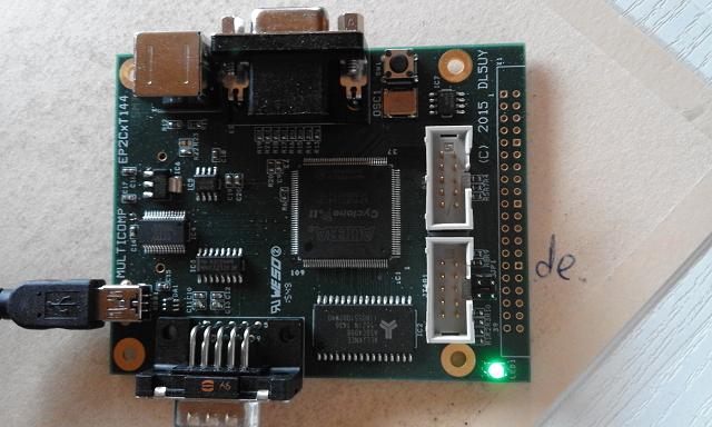
First I used Grant's approach of using that readily available FPGA board and adding the required peripherals around it (RAM, PS/2 keyboard connector, VGA connector, SD card holder), It was time consuming work, especially since some of my friends were interested in it, too. Also, I wanted a larger FPGA than the EP2C5T144 on that board.
So I sat down a looong weekend in December 2015, used my older OrCad to enter the circuit diagram (basically identical to Grant's), added some extras and made the layout. Ordered 10 boards.
Three boards were hand-soldered by a friend and me!
Circuit diagram: multicomp.pdf
See also: KIM-1 AddOn for Multicomp
You can find this board for less than €50.00 on your favorite marketplace:
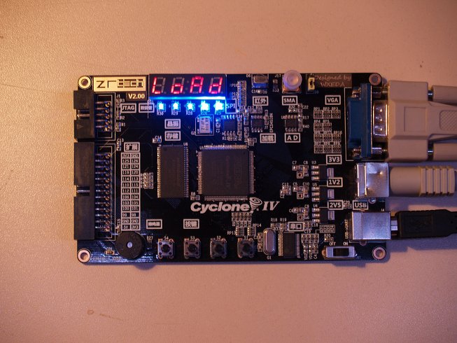
It has an EP4CE6, 32MByte SDRAM, 4MByte SPI FLASH, RGB565 VGA output, PS/2 keyboard connector and a USB serial converter.
Unfortunately, this board has no SD-Card holder.
The 4 MByte SPI FLASH, however, might hold a moderate CP/M system.
It has no extra available I/O pins. The 26-pin expansion connector on the left just parallels the RGB565+HSync+VSync pins
Also, this board got only the 10-pin JTAG connector, and not the 10-pin serial EEPROM programming connector. That is a bit inconvienient since programming the EEPROM with the FPGA bitstream is a more complex process than just "blasting" the bitstream into the EEPROM.